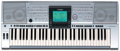
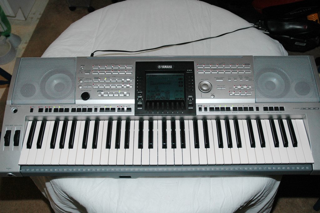
 If you have
a Yamaha PSR arranger keyboard that has suddenly lost a note (very often
an "A" key),
you most likely have a contact strip that needs replacement.
If you have
a Yamaha PSR arranger keyboard that has suddenly lost a note (very often
an "A" key),
you most likely have a contact strip that needs replacement.
I found this to be a quite simple job to tackle at home provided you take your time, and take care.
Overview
Although this range of keyboards are marketed as "Touch Sensitive," in actual fact, they are velocity sensitive. The actuation, and strength of a note played is determined by the velocity at which a piece of carbon approaches a sensor.
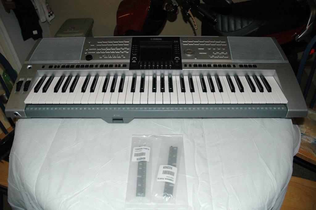
These small pieces of carbon are contained in a rubber substrate and it is this rubber that, over time, can perish and so cause mis-alignment of the carbon and these "missing" notes. These relatively inexpensive parts are available from Yamaha, and can be ordered online at: Yamaha24x7.com. Currently, the part number is: VU32840R. Note that this is a replacement for part number VU328400 which, when I ordered recently, was actually cheaper than the old part number. These contact strips come in lengths of one octave (from C to C), so if you have more than one note missing that spans more than an octave C to C, you will need more than one strip.
Preparation
 I
would suggest working on the keyboard on a soft surface in a dust-free environment.
In my case, I simply used a table covered in a quilt (comforter).
I
would suggest working on the keyboard on a soft surface in a dust-free environment.
In my case, I simply used a table covered in a quilt (comforter).
A very minimum toolset is required for this job:
- Phillips (cross-head) screwdriver
- Small flat-head (blade) screwdriver
Process
Turn the keyboard upside down and support the front of the unit (in front of the keys with soft objects that will keep any undue pressure off the keys themselves. These supports can be placed just in front of the keys - where the symbols for the drum parts are located).
Remove all screws you find from the bottom of the unit. These screws are not all the same size so I would recommend coming up with some system to ensure their correct placement on reassembly. I simply placed them aside in the correct order and orientation for the keyboard, but other methods have been suggested. If you really want to be sure, you could loosen the screws, but leave them in place, and then put some tape over the holes so that they can not fall out.
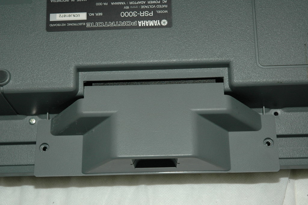 The most important part of the disassembly is that you have to remove
the mount for the card reader, remove the card reader from the mount, and
then tuck the circuit board and reader through the hole and into the inside
of the unit.
The most important part of the disassembly is that you have to remove
the mount for the card reader, remove the card reader from the mount, and
then tuck the circuit board and reader through the hole and into the inside
of the unit.
This is to enable you to separate the two halves of the unit. If you try to separate the halfs without doing this, you may damage the unit as the ribbon connector is not long enough to allow separation.
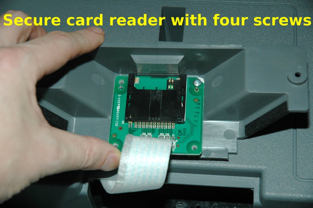
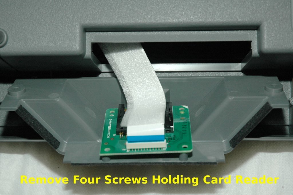 Remove the
four screws holding the card reader to the plastic assembly...
Remove the
four screws holding the card reader to the plastic assembly...
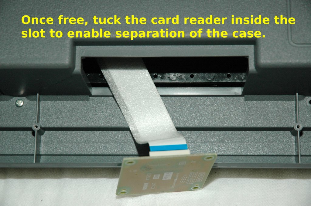 And tuck
the card reader though the hole making sure that it rests on the what
is now the lower half of the keyboard. Basically, we are ensuring
that we can lift the bottom part of the keyboard off leaving the card reader
attached to the other half.
And tuck
the card reader though the hole making sure that it rests on the what
is now the lower half of the keyboard. Basically, we are ensuring
that we can lift the bottom part of the keyboard off leaving the card reader
attached to the other half.
 Be very careful
when lifting the bottom half of the keyboard as the speakers are contained
in this part. You will not be able to completely separate the parts because
the wires for the speakers will still be attached to the part you are lifting, but
be very careful not to drag the speakers against the other part of the keyboard.
Be very careful
when lifting the bottom half of the keyboard as the speakers are contained
in this part. You will not be able to completely separate the parts because
the wires for the speakers will still be attached to the part you are lifting, but
be very careful not to drag the speakers against the other part of the keyboard.
When you have got enough clearance, you can place the section you are lifting behind the other part as there will be enough length on the speaker wires to enable this. Do not strain the speaker wires!
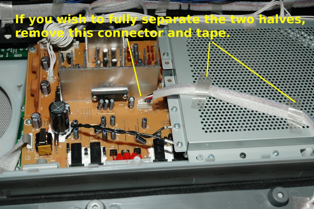 At this stage,
you can decide if you wish to work with the arrangement as is, or completely
separate the two halves of the keyboard.
At this stage,
you can decide if you wish to work with the arrangement as is, or completely
separate the two halves of the keyboard.
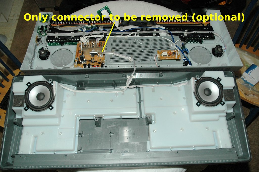
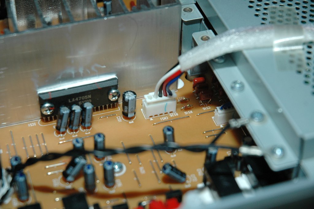
Should you wish to separate the two halves, you simply have to remove the one speaker connector as shown in the pictures.
Closer view of the speaker connector - should you decide to completely separate the two halves (optional).

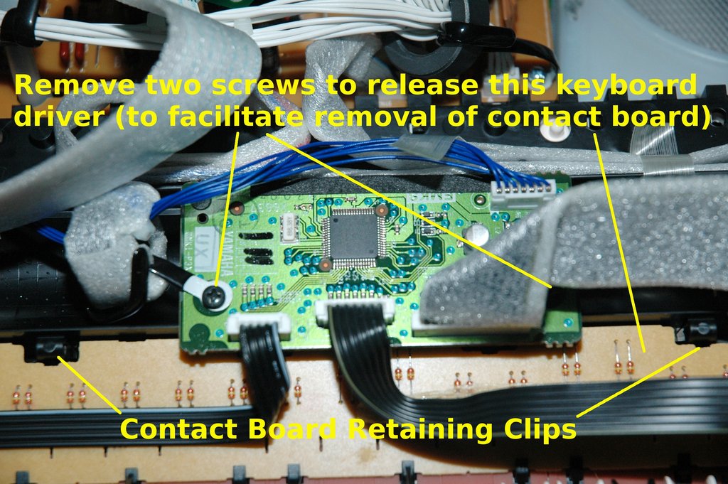 Now,
we have to release the keyboard driver circuit board. This is to ease removal
of the contact board. You don't have to disconnect anything - simply remove
the two screws shown so as to be able to move that board out of the way.
Now,
we have to release the keyboard driver circuit board. This is to ease removal
of the contact board. You don't have to disconnect anything - simply remove
the two screws shown so as to be able to move that board out of the way.
Also shown in this picture are the clips that hold the contact board in place. It is this board that holds the rubber contact strip in place.
This contact board is actually in three separate sections. You only need to release the section that is over the contact strip you need to replace. Of couse, remember that the board is upside-down at this stage, so put a little thought into it before you remove the wrong section!
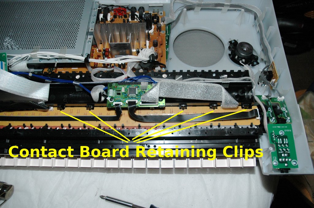 Removal
of the contact board is achieved simply by pushing gently on the retaining
clips (shown in the picture) and gently prising
the board up as you go.
Removal
of the contact board is achieved simply by pushing gently on the retaining
clips (shown in the picture) and gently prising
the board up as you go.
 Note
that there is no need to disconnect any wires to achieve any of this. Once
this contact board has been removed, you have access to the contact strip
itself. In this image, and the one following, you can actually see the collapsed
section of the contact strip that was causing my problem.
Note
that there is no need to disconnect any wires to achieve any of this. Once
this contact board has been removed, you have access to the contact strip
itself. In this image, and the one following, you can actually see the collapsed
section of the contact strip that was causing my problem.
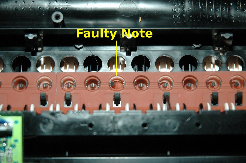 Closer
view showing the faulty note.
Closer
view showing the faulty note.
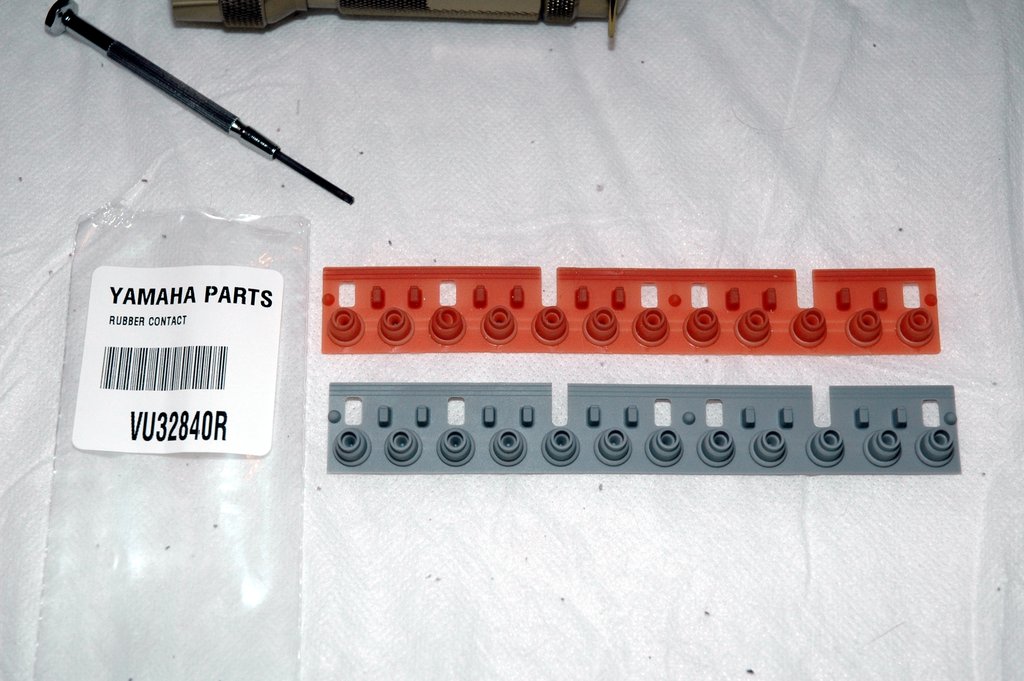 Old strip
removed, and replacement strip waiting to be fitted.
Old strip
removed, and replacement strip waiting to be fitted.
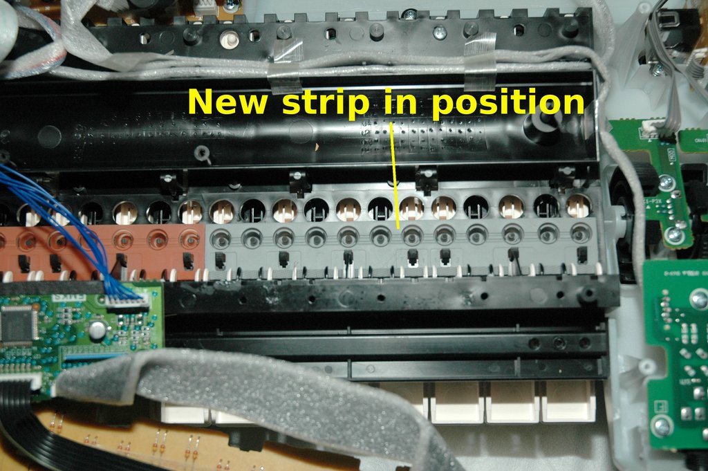 Take great
care that the new strip is seating correctly. Nearest to you, it fits under
the "hooks" that are on the bottom of the black and white keys. I put my
palms underneath the keyboard and depressed the keys a little to facilitate
seating of the strip.
Take great
care that the new strip is seating correctly. Nearest to you, it fits under
the "hooks" that are on the bottom of the black and white keys. I put my
palms underneath the keyboard and depressed the keys a little to facilitate
seating of the strip.
The "turrets" of the contact strip have to fit into the holes and you will
likely feel when they "plop" into place. Check each "turret" to make sure
it is seating correctly. Take your time with this part of the job as
an incorrectly placed contact strip will mean you will have to do this job
over again!
Now, replace
the contact board taking care that you don't displace the new contact strip.
It goes in with the end toward you first and then gently press down at each
clip until you hear the "click" as the clip takes hold.
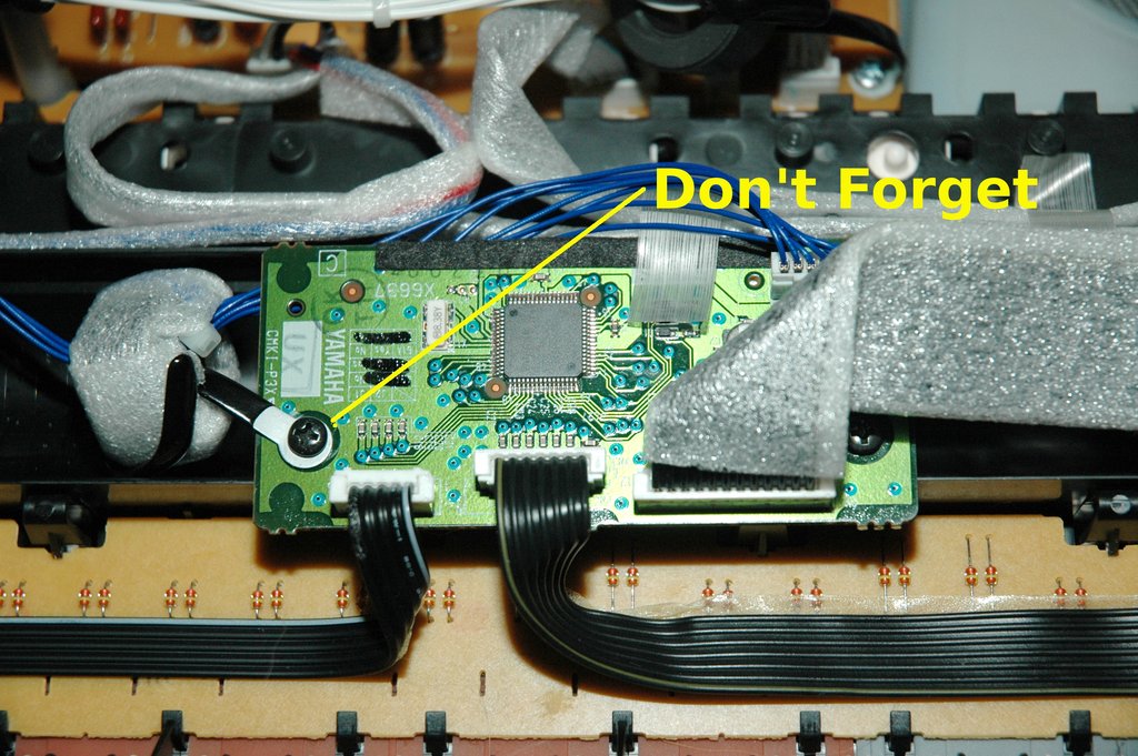 Replace
the keyboard driver panel that you removed earlier. Don't forget to replace
the holder eye as shown in the picture.
Replace
the keyboard driver panel that you removed earlier. Don't forget to replace
the holder eye as shown in the picture.
If you completely
separated the two halves earlier in the process, reconnect the speaker cable,
and carefuly marry the two halves of the unit back together again.
Be careful that you don't allow the speakers to be damaged by contact with other parts of the keyboard!
 Pull the
card reader back through the hole and re-attach the card reader to the plastic
mount. I found this process easiest by simply doubling back the card reader
and placing it flat on the underside of the keyboard.
Pull the
card reader back through the hole and re-attach the card reader to the plastic
mount. I found this process easiest by simply doubling back the card reader
and placing it flat on the underside of the keyboard.
 Fit the
card reader mount back onto the base of the keyboard. Note that the black
lip goes inside the hole.
Fit the
card reader mount back onto the base of the keyboard. Note that the black
lip goes inside the hole.
The front section clips into place. Connect with the two screws.
 As a "sanity
check" at this stage, you may wish to carefully turn the keyboard the right
way up (remember, you haven't screwed it together yet, so take care), and
power the keyboard up to make sure that your repair was succesful and you
now have a fully functioning keyboard.
As a "sanity
check" at this stage, you may wish to carefully turn the keyboard the right
way up (remember, you haven't screwed it together yet, so take care), and
power the keyboard up to make sure that your repair was succesful and you
now have a fully functioning keyboard.
I had faith and didn't test until it was all back together again.
Replace all screws that were removed earlier, turn the keyboard the correct
way up and you should be done!
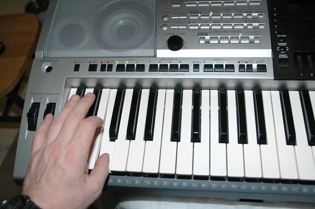 Power up
the keyboard. Now is the time to practice your chromatic scales. Run through
all the notes to check that all are playing. Also check that you have correct
touch sensitivity restored.
Power up
the keyboard. Now is the time to practice your chromatic scales. Run through
all the notes to check that all are playing. Also check that you have correct
touch sensitivity restored.
Step back, enjoy your work!
This page updated on September 20, 2024 .